
Page 19 - ELECTRONICON_Key-Components-50Hz
P. 19
DESIGN DRAWINGS
CAPAGRIP K, L, M AND CAPAGRIP II :
TM
TM
EASE OF ASSEMBLY WITH HIGH DEGREE OF PROTECTION
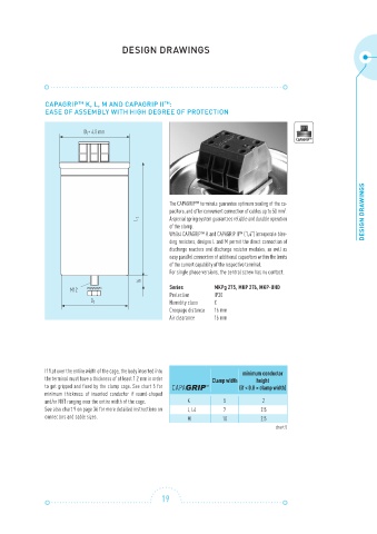
D+ 4.5 mm
1
CAPAGRIP TM
The CAPAGRIP™ terminals guarantee optimum sealing of the ca-
pacitors, and offer convenient connection of cables up to 50 mm . DESIGN DRAWINGS
2
L 1 A special spring system guarantees reliable and durable operation
of the clamp.
Whilst CAPAGRIP™ K and CAPAGRIP II™ (“L4”) incorporate blee-
ding resistors, designs L and M permit the direct connection of
discharge reactors and discharge resistor modules, as well as
easy parallel connection of additional capacitors within the limits
of the current capability of the respective terminal.
For single phase versions, the central screw has no contact.
6
1
M12 Series MKPg 275, MKP 276, MKP-UHD
Protection IP20
Humidity class C
D 1
Creepage distance 16 mm
Air clearance 16 mm
If flat over the entire width of the cage, the body inserted into minimum conductor
the terminal must have a thickness of at least 1.2 mm in order Clamp width height
to get gripped and fixed by the clamp cage. See chart 5 for (if < 0.8 × clamp width)
minimum thickness of inserted conductor if round-shaped
and/or NOT ranging over the entire width of the cage. K 5 2
See also chart 9 on page 36 for more detailed instructions on L, L4 7 2.5
connectors and cable sizes. M 10 2.5
chart 5
19