
Page 48 - ELECTRONICON_Key-Components-50Hz
P. 48
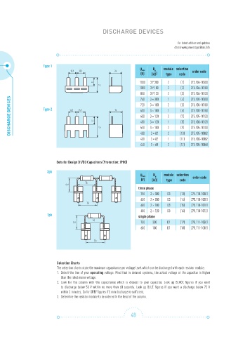
DISCHARGE DEVICES


                                                                                          for latest edition and updates
                                                                                        check www.powercapacitors.info


                       Type 1
                                                                       U max   R    module selection
                                    15,2  15,2            24                  N                  order code
                                                                       (V)   (kΩ )   type  code
                                                5                      1000  3 Y 300  2    (1)  275.106-10300
                                                1
                                                   7
                                                                       1000  3 Y 180  2    (2)  275.106-10180
                                                   2
                                                                            3 Y 120
                                                                       850  3 × 300  2 1 2  (3)  275.106-10120
      DISCHARGE DEVICES  Type 2     15.2  15.2  5  1  7   24           600  3 × 180  1 2 1 2  (6)  275.100-10180
                                                                                           (4)
                                                                       760
                                                                                                275.100-10300
                                                                            3 × 180
                                                                       720
                                                                                           (5)
                                                                                                275.105-10180
                                                                                                275.105-10120
                                                                       600
                                                                                           (7)
                                                                            3 × 120
                                                                                           (8)
                                                                            3 × 120
                                                                       480
                                                                                                275.100-10120
                                                                            3 × 100
                                                                       530
                                                                                           (9)
                                                                                                275.105-10100
                                                   4
                                                                       480
                                                                       400  3 × 82   2 1   (10)  275.105-10082
                                                                                                275.100-10082
                                                                            3 × 82
                                                                                           (11)
                                                                       440  3 × 68   2     (12)  275.105-10068
                             Sets for Design D1/D3 Capacitors (Protection: IP00)
                         3ph
                                                                       U max   R   N  module selection  order code
                                                                        (V)  (kΩ)    type  code
                  16                        16
          2                        2
          1                        1
                                                                      three phase
                                                                       750  2 × 300  D3    (13)  275.110-10301
                                                                       630  2 × 200  D3    (14)  275.110-10201
                   16                       16
                                                                       600  2 × 180  D3    (15)  275.110-10181
                                                                       480  2 × 120  D3    (16)  275.110-10121
                         1ph                                          single phase
                                               16                        16
                                       2                        2      750   300     D1    (17)  275.111-10301
                                       1                        1
                                                                       600   180     D1    (18)  275.111-10181
                                                16                       16


                              Selection Charts
                              The selection charts state the maximum capacitance per voltage level which can be discharged with each resistor module:
                              1.    Select the line of your operating voltage. Mind that in detuned systems, the actual voltage at the capacitor is higher
                                  than the rated mains voltage.
                              2.   Look for the column with the capacitance which is closest to your capacitor. Look up BLACK figures if you want
                                 to discharge below 50 V within no more than 60 seconds. Look up BLUE figures if you want a discharge below 75 V
                                  within 3 minutes. Go for GREY figures if 5 min discharge is sufficient.
                              3.    Determine the resistor module to be ordered in the head of the column.


                                                                   48