Page 16 - 200.003-020017
P. 16
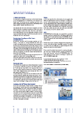
MKPg-Druck_fürweb.qxp 13.09.2012 09:26 Seite 14 IMPORTANT IMPORTANT REMARKS 12 Months Limited Warranty Warning: All our products are designed, manufactured, and tested with the high- It has to be noted that this safety system can act properly only est care and workmanship. The satisfaction of our customers is our within the permitted limits of loads and overloads. The simple pres- highest goal. We therefore warrant remedying any defect in the ence of a safety mechanism does not mean that catastrophic fail- goods resulting from faulty design, materials or workmanship, which ures are completely impossible. Strong overvoltages, permanent exter- appears within 12 months from the date of sale. nal heat, and heavy current overload, e.g. during harmonic resonances may cause sudden, uncontrollable rise of temperature and pressure This warranty does not cover defects due to improper use of the inside the can which may not leave sufficient time for the BAM™ goods or operation at conditions exceeding the rated values stated to act properly, and result in explosion and fire. in the catalogue or special data sheet. Nor does it cover defects due to faulty maintenance or incorrect installation, alterations or faulty Safety repairs undertaken by the Buyer. Finally the warranty does not cover ELECTRONICON will not indemnify or be responsible for any kind of normal wear and tear or deterioration. damages to persons or property due to the improper application of any capacitors or reactors purchased from ELECTRONICON or its dis- Protection Against Overvoltages and Short Circuits: tributors. The capacitors and reactors should only be used for the appli- Self-Healing Dielectric cation intended. All dielectric structures used in our power capacitors are “self- healing”: In the event of a voltage breakdown the metal layers Mind that electrical or mechanical misapplication of capacitors and around the breakdown channel are evaporated by the temperature reactors can become hazardous. Misapplied capacitors can explode of the electric arc that forms between the electrodes. They are removed or catch fire and cause bodily injury or property damage due to the within a few microseconds and pushed apart by the pressure gen- expulsion of material or metal fragments. erated in the centre of the breakdown spot. An insulation area is formed which is reliably resistive and voltage proof for all operating require- Please consult the detailed instructions for mounting and applica- ments of the capacitor. The capacitor remains fully functional dur- tion stated in our Catalogue brochure “Capacitors and Reactors For ing and after the breakdown. Power Factor Correction”, and on the ELECTRONICON website. If in For voltages within the permitted testing and operating limits the doubt about how to connect, operate, or discharge a capacitor, con- capacitors are short-circuit- and overvoltage-proof. sult ELECTRONICON engineering. They are also proof against external short circuits as far as the result- ing surge discharges do not exceed the specified surge current lim- For more detailed information, please order our comprehensive catalogue its. “Capacitors and Reactors for Power Factor Correction”, and the “General Safety Advice for Power Capacitors” issued by the German Electrical and Electronic Manufacturer’s Association (ZVEI). Mounting and Cooling The useful life of a capacitor may be reduced dramatically if exposed See our “General Conditions” for details on Warranty and Product liability. to excessive heat. Typically an increase in the ambient temperature of 7°C will halve the expected life of the capacitor. Make sure to obey the permitted operating temperatures of ambient temperature class D (max. temperature 55°C, max. average over 24hrs. 45°C, max. average over 365 days 35°C). To avoid overheating the capacitors must be allowed to cool unhin- dered and should be shielded from external heat sources. We rec- ommend forced ventilation for all applications with detuning reactors. Give at least 20mm clearance between the capacitors for natural or forced ventilation, and do not place them directly above or next to heat sources such as detuning or tuning reactors, bus bars, etc. Functioning of the BAM™ (Break Action Mechanism) In the event of overvoltage or thermal overload or ageing at the end of the capacitor's useful service life, an increasing number of self- healing breakdowns may cause rising pressure inside the capacitor. To prevent it from bursting, the capacitor is fitted with an obliga- tory “break action mechanism” (BAM). The BAM™ is based on an atten- uated spot at one of the connecting wires inside the capacitor. With rising pressure the case begins to expand, mainly by opening the folded crimp and pushing the lid upwards. As a result, the prepared connecting wire is separated at the attenuated spot, and the cur- rent path is interrupted irreversibly. 14