
Page 59 - ELECTRONICON_Key-Components-50Hz
P. 59
DEFINITIONS AND SELECTION CRITERIA
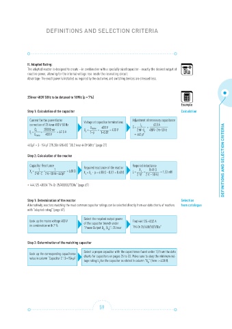
II. Adapted Rating:
The adapted reactor is designed to create – in combination with a specially sized capacitor - exactly the desired output of
reactive power, allowing for the internal voltage rise inside the resonating circuit.
Advantage: The exact power is installed as required by the customer, and switching devices are stressed less.
25kvar 400V 50Hz to be detuned to 189Hz (p = 7%)
Example
Step 1: Calculation of the capacitor Calculation
Current for the power factor
Voltage at capacitor terminations Adjustment of necessary capacitance
correction of 25 kvar 400 V 50 Hz C = = 62.5 A
I
C
25000 var U = U mains 400 V = 430 V 2 πf · U 430 V · 2 π · 50 Hz
=
I = = = 62.5 A C 1-p 1-0.07 C
Q c
C
U mains 400 V = 463 μF
463μF = 3⋅ 154μF 275.286-515400 “28.2 kvar 440V 50Hz” (page 27)
Step 2: Calculation of the reactor
DEFINITIONS AND SELECTION CRITERIA
Capacitor Reactance Required reactance of the reactor Required inductance
X
1
1
X = = = 6.88 Ω X = X ⋅ p = 6.88 Ω ⋅ 0.07 = 0.48 Ω L = = 0.48 Ω = 1.53 mH
L
C
2 πf · C 2 π · 50 Hz · 463 μF L C 2 πf 2 π · 50 Hz
> 444.125-4032A “Fk-Dr 25/400/50/7/Dla“ (page 67)
Step 1: Determination of the reactor Selection
Alternatively, reactors matching the most common capacitor ratings can be selected directly from our data charts of reactors from catalogue
with “adapted rating” (page 67):
Look up the mains voltage 400 V Select the required output power Find 444.125-4032 A
of the capacitor branch under
in combination with 7 %
“Power Output Q (U )”: 25 kvar “FK-Dr 25/400/50/7/Dla“
N
LC
Step 2: Determination of the matching capacitor
Look up the corresponding capacitance Select a proper capacitor with the capacitance found under 1.) from the data
value in column “Capacitor C”: 3 × 154 μF charts for capacitors on pages 26 to 33. Make sure to obey the minimum vol-
tage rating U for the capacitor as stated in column “U ” (here: > 430 V).
N
C
59