
Page 57 - ELECTRONICON_Key-Components-50Hz
P. 57
DEFINITIONS AND SELECTION CRITERIA
Rated Inductance L N
Inductance rating of the reactor, measured at rated current I , in mH (Milli-Henry). Mean value across the three phases.
N
Rated Voltage U N
Root mean square value of the permissible value of sinusoidal AC voltage in continuous operation (mains voltage). The rated
voltage of the reactors indicated in the data charts and the permissible overvoltage limits specified in IEC 60831 and DIN EN
50160 must not be exceeded even in cases of malfunction.
Capacitor Voltage U C
Required voltage strength of the capacitor. The series connection of capacitor and reactor causes a voltage rise at the capacitor
terminals as described by the following formula which must be considered when selecting a capacitor for the application.
U N
U = 400 V U C = p = 430.1 V
N
p = 7 % 1 - Example
100%
The capacitor to be selected must have a voltage strength of at least 430 V. DEFINITIONS AND SELECTION CRITERIA
Detuning Factor p
Ratio between the reactances of reactor X and corresponding capacitor X (in %). p = 100% · X L
L
C
X C
Series Resonance Frequency f r 100 %
The detuning factor determines the series resonance frequency between reactor f = f · p
r
N
and capacitor which in turn is important for the blocking and filtering effect.
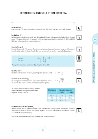
The standard reactors listed in this catalogue have been
designed for common detuning factors and resonance Detuning factor Resonance frequency f r
frequencies as shown in chart 11: p f n = 50 Hz f n = 60 Hz
5.67 % 210 Hz 252 Hz
7 % 189 Hz 227 Hz
14 % 134 Hz -
chart 11
Rated Power of the Detuned System Q LC
Care must be taken when stating the reactor power in order to avoid misunderstanding. As a rule, the rated power of a reactor
does not describe its real reactance but either the reactive power of the capacitor to be detuned, or the total output of the en-
tire LC-circuit at rated system voltage U . N
There are two principal approaches which are described in detail on the following pages.
57