
Page 38 - ELECTRONICON_Katalog_PFC-60Hz
P. 38
CAPACITOR CONTACTORS
1301A SERIES
Power capacitors may enter high-frequency resonances with
nearby inductances when being connected to the mains. Though
vanishing within a few microseconds, such resonances lead to
very high current surges which, if occurring regularly, may da-
mage the capacitor elements. In accordance with IEC EN 60831-
1/2, the annual number of switching operations for our standard
CAPACITOR CONTACTORS For flawless operation of our capacitors, we strongly recommend using special capacitor contactors with inrush-limiting (“leading”)
capacitors is therefore recommended not to exceed 5000…6000
counts p.a. Special capacitors suitable for a higher annual
number of switchings are available on request.
contacts. Such devices connect a preload channel several milliseconds prior to closing their main contact. This channel is choked
down by special current limiting resistors and substantially softens the initial switching inrush surge, protecting the capacitors from
destructive current surges and the contactors from premature deterioration or welding.
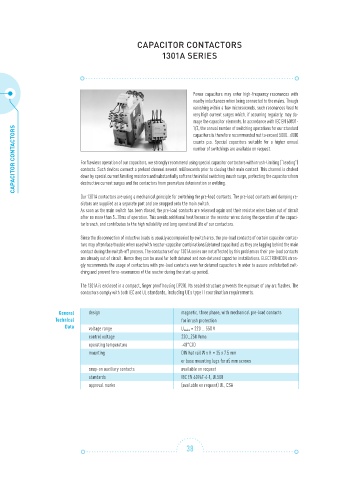
Our 1301A contactors are using a mechanical principle for switching the pre-load contacts. The pre-load contacts and damping re-
sistors are supplied as a separate part and are snapped onto the main switch.
As soon as the main switch has been closed, the pre-load contacts are released again and their resistor wires taken out of circuit
after no more than 5…10ms of operation. This avoids additional heat losses in the resistor wires during the operation of the capaci-
tor branch, and contributes to the high reliability and long operational life of our contactors.
Since the disconnection of inductive loads is usually accompanied by switch arcs, the pre-load contacts of certain capacitor contac-
tors may often face trouble when used with reactor-capacitor combinations (detuned capacitors) as they are lagging behind the main
contact during the switch-off process. The contactors of our 1301A series are not affected by this problem as their pre-load contacts
are already out of circuit. Hence they can be used for both detuned and non-detuned capacitor installations. ELECTRONICON stron-
gly recommends the usage of contactors with pre-load contacts even for detuned capacitors in order to assure undisturbed swit-
ching and prevent ferro-resonances of the reactor during the start-up period.
The 1301A is enclosed in a compact, finger proof housing (IP20). Its sealed structure prevents the exposure of any arc flashes. The
contactors comply with both IEC and UL standards, including UL’s type II coordination requirements.
General design magnetic, three phase, with mechanical pre-load contacts
Technical for inrush protection
Data voltage range U mains = 220 … 550 V
control voltage 220…250 Vrms
operating temperature -40°C/D
mounting DIN hat rail W x H = 35 x 7.5 mm
or base mounting lugs for ø5 mm screws
snap-on auxiliary contacts available on request
standards IEC EN 60947-4-1, UL508
approval marks (available on request) UL, CSA
38