
Page 56 - ELECTRONICON_Katalog_PFC-60Hz
P. 56
DEFINITIONS AND SELECTION CRITERIA
Dissipation Power P eff
Sum of all iron-, copper-, and stray field losses at max. specified overvoltage and harmonic content. Depending on the detuning
factor, the effective dissipation power of our reactors is between 4 and 6 W/kvar.
Rated Current (also: Fundamental Current) I N
RMS value of the current – caused by the series-connected capacitor – at rated voltage and frequency, excluding harmonic
distortion, switching transients, and tolerance of capacitance.
RMS Current I eff
Current load on the reactor in permanent operation, caused by the fundamental wave plus harmonics in the system. For all data
given in this catalogue, we are presuming a 10 % increase of the fundamental current I , resulting from voltage tolerances as
N
permitted by DIN EN 50160: I = (I +I +I + + I ) I = 1.1 ⋅ I N
2
2
2
2
5 · · ·
n
3
1
eff
1
Maximum Current Rating I and Current Linearity
DEFINITIONS AND SELECTION CRITERIA
lin
Maximum current, up to which the inductance of the reactor remains “linear”, i.e. does not decrease by more than 5 % below its
rated inductance. This maximum current is specified in the data charts as a multiple K of the fundamental current:
I = K ⋅ I (I ≥ 0.95 I !) K ... overcurrent factor
lin
N
N
lin
Exceeding I or I will cause increased power losses inside the reactor and may result in its thermal destruction. We recom-
rms
lin
mend thermal monitoring of the reactors by means of the integrated temperature switch, or the use of switching devices with
overcurrent relays in the capacitor circuit, to protect against overloads.
Ambient Operating Conditions
Permissible ambient conditions for safe operation of the reactor. For our reactors, we specify the climate category in the data
charts as “CTT” in accordance with DIN EN 50019 and DIN EN 60934/IEC 60439-1:
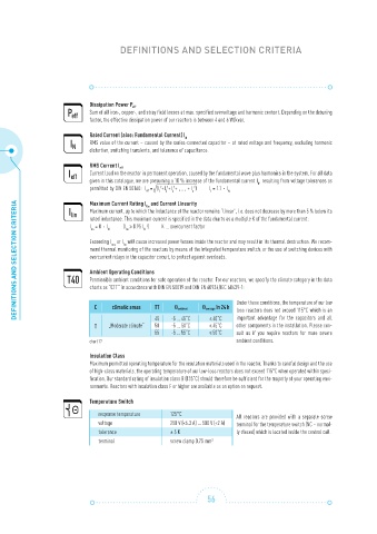
C climatic areas TT Θ ambient Θ average in 24 h Under these conditions, the temperature of our low
loss reactors does not exceed 115°C which is an
45 -5 ... 45˚C ≤ 40˚C important advantage for the capacitors and all
T „Moderate climate“ 50 -5 ... 50˚C ≤ 45˚C other components in the installation. Please con-
55 -5 ... 55˚C ≤ 50˚C sult us if you require reactors for more severe
chart 12 ambient conditions.
Insulation Class
Maximum permitted operating temperature for the insulation materials used in the reactor. Thanks to careful design and the use
of high-class materials, the operating temperature of our low-loss reactors does not exceed 115°C when operated within speci-
fication. Our standard rating of insulation class B (135˚C) should therefore be sufficient for the majority of your operating envi-
ronments. Reactors with insulation class F or higher are available as an option on request.
Temperature Switch
response temperature 125°C All reactors are provided with a separate screw
voltage 250 V (<6.3 A) … 500 V (<2 A) terminal for the temperature switch (NC – normal-
tolerance ± 5 K ly closed) which is located inside the central coil.
terminal screw clamp 0.75 mm 2
56