
Page 32 - ELECTRONICON_Katalog_PFC-60Hz
P. 32
MOUNTING INSTRUCTIONS
»!« Safe operation of the capacitors can be expected only if all electrical and thermal specifications as stated on the label, in
the data sheets or catalogues and the following instructions are strictly observed. ELECTRONICON does not accept respon-
sibility for whatever damage may arise out of a non-observance.
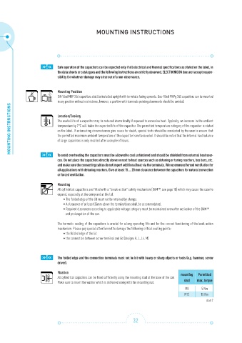
Mounting Position
Oil-filled MKP 266 capacitors shall be installed upright with terminals facing upwards. Gas-filled MKPg 265 capacitors can be mounted
in any position without restrictions, however, a position with terminals pointing downwards should be avoided.
MOUNTING INSTRUCTIONS Location/Cooling
The useful life of a capacitor may be reduced dramatically if exposed to excessive heat. Typically, an increase in the ambient
temperature by 7°C will halve the expected life of the capacitor. The permitted temperature category of the capacitor is stated
on the label. If extenuating circumstances give cause for doubt, special tests should be conducted by the user to ensure that
the permitted maximum ambient temperature of the capacitor is not exceeded. It should be noted that the internal heat balance
of large capacitors is only reached after a couple of hours.
»!«
To avoid overheating the capacitors must be allowed to cool unhindered and should be shielded from external heat sour-
ces. Do not place the capacitors directly above or next to heat sources such as detuning or tuning reactors, bus bars, etc.
and make sure the connecting cables do not import additional heat via the terminals. We recommend forced ventilation for
all applications with detuning reactors. Give at least 15 ... 20 mm clearance between the capacitors for natural convection
or forced ventilation.
Mounting
All cylindrical capacitors are fitted with a ”break-action” safety mechanism (BAM™, see page 18) which may cause the case to
expand, especially at the crimp and at the lid.
• The folded edge of the lid must not be retained by clamps.
• A clearance of at least 35mm above the terminations shall be accommodated.
• Required clearances according to applicable voltage category must be maintained even after activation of the BAM™
and prolongation of the can.
The hermetic sealing of the capacitors is crucial for a long operating life and for the correct functioning of the beak action
mechanism. Please pay special attention not to damage the following critical sealing points:
• the folded edge of the lid
• the connection between screw terminal and lid (designs K, L, L4, M)
»!« The folded edge and the connection terminals must not be hit with heavy or sharp objects or tools (e.g. hammer, screw
driver).
Fixation mounting Permitted
All cylindrical capacitors can be fixed sufficiently using the mounting stud at the base of the can.
Make sure to insert the washer which is delivered along with the mounting nut. stud max. torque
M8 5 Nm
M12 15 Nm
chart 7
32