
Page 23 - ELECTRONICON_Katalog_PFC-60Hz
P. 23
DEFINITIONS AND SELECTION CRITERIA
Current rating I N
RMS value of the current at rated voltage and frequency, excluding harmonic distortion, switching transients, and capacitance
tolerance.
Q C
It can be calculated by the formula I = = 2πf · C · U and is not stated in the data charts.
U N N
Pulse current strength I S
Depending on construction and voltage rating, the design of our capacitors permits short term inrush currents of 100…400 × I
N
and – in accordance with IEC 60831 – up to 5000 switching operations per annum as standard. However, when switching capa-
citors in automatic capacitor banks without detuning reactors, higher loads are very often the case. This may generate negative
effects on the operational life, especially with capacitors which are frequently connected and disconnected (e.g. primary stages DEFINITIONS AND SELECTION CRITERIA
in automatic capacitor banks). Moreover, even detuned capacitors may experience switching currents exceeding the permissible
maximum current of the reactor and causing consequential damage to both capacitor and reactor.
We strongly recommend the use of special capacitor contactors with inrush limiting resistors, or other adequate »!«
devices for limitation of the peak inrush currents.
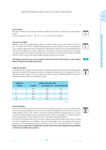
Temperature category
The average useful life of a capacitor depends very much on the ambient temperatures it is operated at. The permissible operating
temperatures are defined by the temperature class stated on the label which contains the lower limit temperature (-50°C) and a
letter, which describes the values of the upper limit temperatures. Chart 6 is based on IEC 60831 and details the maximum permitted
ambient temperatures for capacitors in each tem pera ture category.
temperature ambient temperature limits
category maximum max. average 24 hrs max. average 365 days
B 45°C 35°C 25°C
C 50°C 40°C 30°C
D 55°C 45°C 35°C
60 60°C 50°C 40°C
65 65°C 55°C 45°C
chart 6
Lifetime Statements
Even though all our lifetime statements are based on many years of empirical data, testing and field statistics, they will always
remain just a general prognosis based on data of the past and accelerated laboratory tests which cannot reflect all aspects of
modern operating conditions. The real “lifetime” of our capacitors depends on a multitude of influencing factors, such as ambient
temperatures, operating voltages, frequency of overvoltages, frequency of switching, system faults a.o. The lifetime estimations
given in our data sheets are therefore linked with specific operating conditions (voltage and temperature).
It has also to be noted that any lifetime statement considers a certain percentage of permitted failures within a given lot, reflecting
the fact that any component has a FIT rate (failures in time). Under rated operating conditions, our capacitors can be expected to
have a FIT rate of no more than 300 (corresponding to a maximum failure rate of 3 %) during their initial 100,000 hours of operation..
Please consult our sales teams if in doubt about the specific implications of your intended operating conditions
on lifetime and reliability of our capacitors.
23